Engineering & testing
Railing Masters guard systems are supported by independent field load testing and P.Eng-stamped detail packages. This page publishes the measured results in full.
F. Alibai, P.Eng. · PEO 100206138
Review by JRAMCO Inc. for the sole purpose of framing, glass and anchor structural adequacy, in general conformance with OBC and CDS.
All seven load cases passed.
Static load testing performed by JRAMCO Inc. at 110 Claireport Crescent, Unit 4, Etobicoke, Ontario on 11 November 2025, in general conformance with ASTM E935-13 and ASTM E985.
marks the OBC 4.1.5.14 minimum of 1.0 kN. Bars show the load actually applied.
Glass infill: concentrated load
Tested at 0.9 kN against a 0.5 kN code requirement, applied over a 100 mm × 100 mm area at panel center.
No cracking, delamination or distress at glass holders, channels or mechanical connections.
Test assembly
- Structural aluminum posts and top rail manufactured by Hydro Extrusions
- Laminated glass infill panels
- Mechanically fastened structural connections
- Mechanical anchorage into reinforced concrete slab
A fraction of what the standard allows.
Deflection limits per CSA A500-16, Clause 5.5.1.6. Lower is better; the bar shows measured deflection as a share of the allowable limit.
| Table | Element | Direction | Applied | Deflection | Allowable | Utilization | Residual | Result |
|---|---|---|---|---|---|---|---|---|
| 1A | Intermediate post | Outward | 2.1 kN | 26 mm | 89 mm | 29% |
1.5 / 13 mm | PASS |
| 2A | Intermediate post | Inward | 2.1 kN | 27.5 mm | 89 mm | 31% |
1.5 / 13 mm | PASS |
| 1B | Top rail, mid-span | Outward | 1.96 kN | 36 mm | 56 mm | 64% |
1.5 / 11 mm | PASS |
| 2B | Top rail, mid-span | Inward | 2.1 kN | 36.5 mm | 56 mm | 65% |
1 / 11 mm | PASS |
| 1C | End post | Outward | 1.78 kN | 30.5 mm | 89 mm | 34% |
1.5 / 13 mm | PASS |
| 2C | End post | Inward | 1.78 kN | 19 mm | 89 mm | 21% |
4.5 / 18 mm | PASS |
| C | Glass infill, center | Outward | 0.9 kN | 2.09 mm | — | Serviceability: minimal | 0.09 mm | PASS |
Test configuration: guard height 1070 mm, post spacing 1080 mm. Deflections measured with calibrated laser displacement equipment.
Tested and designed to
| ASTM E935-13 | Performance of Permanent Metal Railing Systems |
| ASTM E985 | Specification for Permanent Metal Railing Systems |
| OBC 4.1.5.14 | Ontario Building Code (2012), Loads on Guards |
| CSA A500-16 | Deflection criteria, Clause 5.5.1.6 |
| CSA S157 | Strength design in aluminum |
OBC 4.1.5.14, loads on guards
- 0.75 kN/m or 1.0 kN concentrated load, whichever governs, applied horizontally at guard height
- 0.5 kN concentrated load applied over a 100 mm × 100 mm area to individual elements (glass infill)
- Specified wind load pressure of 2.0 kPa
- Vertical load provisions reviewed per OBC Clause 4.1.5.14(4)
How the test was run
- Horizontal loads applied incrementally and held until stabilization was achieved
- A preload of approximately 50% of target load applied and released prior to final loading, to assess residual deflection
- Deflections measured using calibrated laser displacement equipment
- Loads increased gradually to the maximum calculated design load, then released to observe permanent deformation or connection distress
What was recorded
- Measured deflections remained within allowable limits for all load cases
- Residual deflection after load release was within acceptable tolerances
- No structural failure, cracking, yielding, loosening or disengagement of posts, anchors, top rail, glass panels or mechanical connections was observed
- Glass infill panels resisted the specified 0.5 kN concentrated load without damage or instability
- Load–deflection behavior was linear and stable throughout each test
— JRAMCO Inc., Field Test Report RT25-330-1111-01. Certified mill test reports from Hydro Extrusions are available on request and confirm that all aluminum extrusions supplied are within specified alloy and temper tolerances and meet applicable material standards.
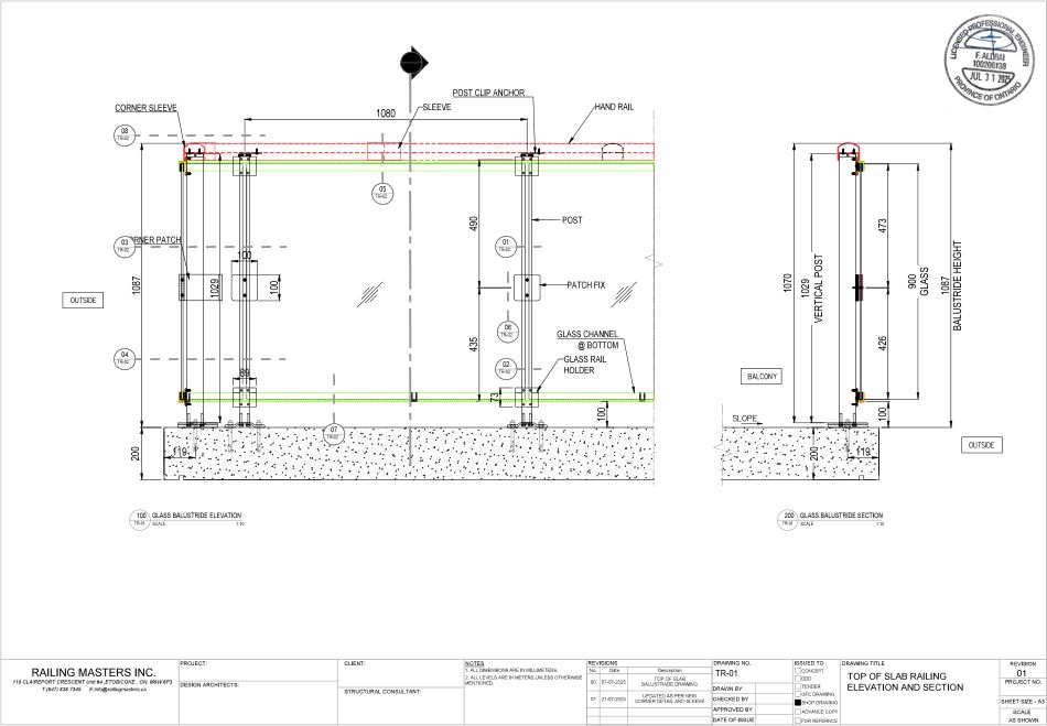
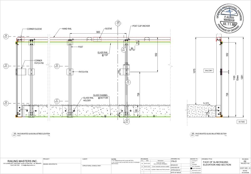
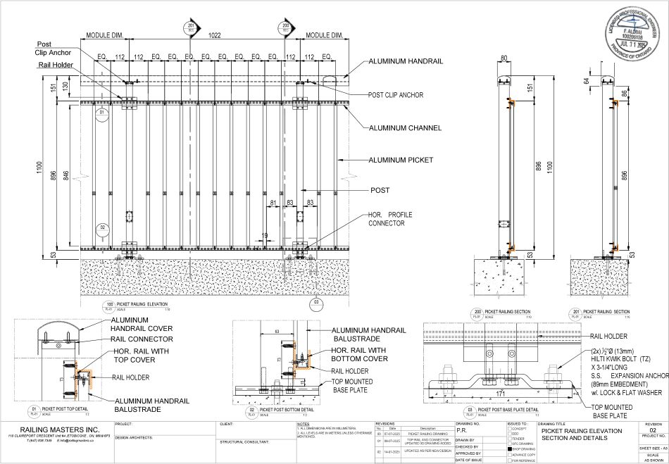
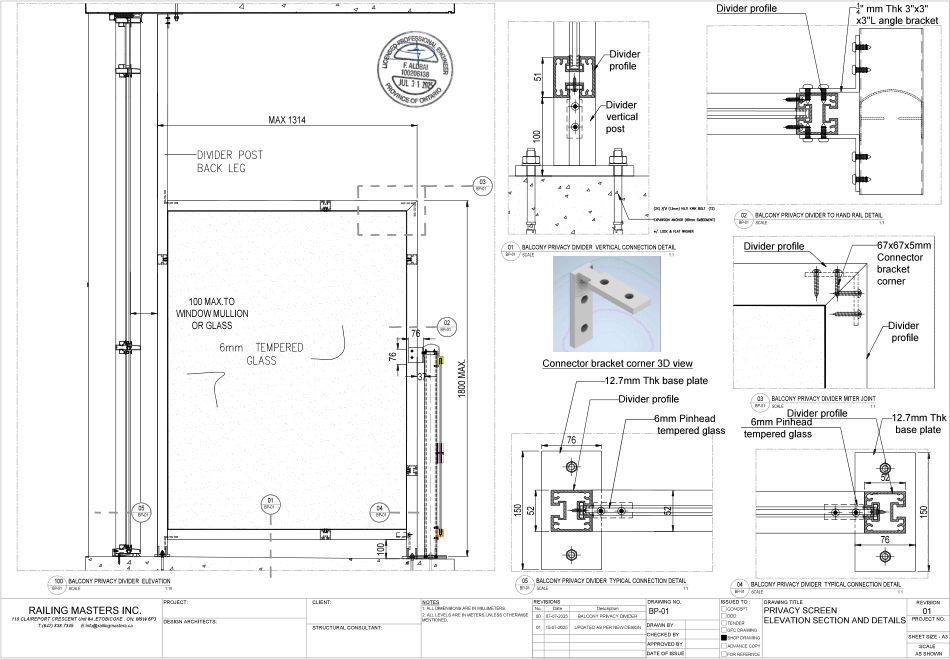
Four detail sets, reviewed and stamped.
Elevation and section sheets from each package. The full sets, with connection details and materials lists, are on the resources page.
Component schedule
Extracted from the stamped materials lists. Fastener schedules are the standard specification; project-specific engineering may vary them.
| Component | Alloy | Specification |
|---|---|---|
| Base plate | 6061-T6 | Anchored to concrete with 2 × ½"⌀ (13 mm) × 3¼" Hilti Kwik Bolt TZ stainless expansion anchors, 89 mm embedment, with lock and flat washer. |
| Railing post | 6061-T6 | Base plate bolted to post with 4 × ⁵⁄₁₆"–18 × 1¾" unpainted fully threaded S.S. T316 bolts, washer and lock washer. 4 × ⅜"–18 tapped to min. 1⅝". |
| Glass rail holder | 6061-T6 | Fastened to post with 4 × #12 × 1" painted pan-head self-tapping stainless screws. |
| Glass channel | 6061-T6 | Fastened to glass rail holder with 2 × #10 × ½" painted pan-head self-tapping stainless screws. |
| Hand rail | 6061-T6 | Fastened to post clip anchor with 2 × #10 × ¾" painted pan-head self-tapping stainless screws. |
| Post clip anchor | 6061-T6 | Installed at top of post, fastened each side of post and to underside of handrail with 2 × #10 × ¾" painted pan-head self-tapping stainless screws. |
| Connecting sleeve, 127 mm | 6061-T6 | Expansion joint at every 50 ft (1520 mm), fastened with 2 × #10 × ¾" screws on one side only. Located where handrail is mounted between two posts; 4 × #10 × ¾" screws, 2 each side. |
| Corner sleeve, 160 mm | 6061-T6 | Fastened to handrail with 4 × #10 × ¾" pan-head self-tapping stainless screws, 2 screws each direction. |
| End cap | 6061-T6 | Painted end cap fastened to stainless angle with 2 × #10 × ¾" painted pan-head self-tapping stainless screws. |
| Stainless angle | S.S. | 25 mm × 25 mm × 2 mm thick × 76 mm long, fastened to end cap and to underside of handrail with #10 × ¾" screws. |
| Glass patch | 6061-T6 | 5 mm neoprene gasket, 3 mm painted aluminum flat 100 × 100 mm, 1.5 mm double-sided tape each side of glass; fastened to post with 2 × #12 × 1¾" painted flat-head self-tapping stainless screws. |
| Gaskets & shims | — | 1.5 mm double-sided tape between glass rail holder and glass channel. PVC horseshoe shims between glass channel and rail holder. Channel gasket inserted into glass channel; rubber gasket at each glass end. |
Send us the elevation. We'll send back the system.
Tell us the mounting condition, guard height and code jurisdiction. We'll come back with the recommended system, a stamped detail set and a materials list you can put straight into the spec.